Operator Panels: Interaction with the Environment
The following sections discuss how to create Operator Panel Specification to allow the user to interact with the environment.
Creating an Operator Panel Specification
In order to create an Operator Panel you first have to create an appropriate component to contain it. In most cases it is ideal to create the enclosing component next to your actual model and then connect this component's outputs to your model's inputs and vice versa.

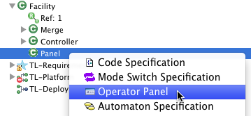
Afterwards right click on the newly created component in the model tree on the left and add an "Operator Panel".
Populating the Operator Panel with items
Once you have added an operator panel to your component and opened it, you may drag & drop an item from the Model Elements View on the right. Place and size the items to your needs and use labels to annotate your widgets. Aside from buttons these will be the only text displayed later during simulation.
There are two type of operator panel items:
- Input Operator Panel Items: These items display data that is input data to the enclosing component, which in general is output data from your model.
- Output Operator Panel Items: These items create output from the enclosing component that can be input to your model.
Push Button
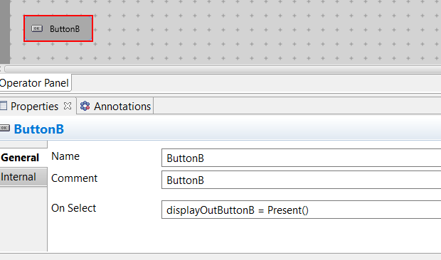
In the property section you can enter the text displayed on the button using the comments text field. More importantly you can enter one or multiple outputs to be performed
upon button selection. In all other times the output assigned will be NoVal.
Toggle Button
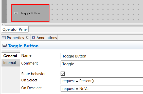
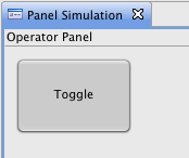
The property section of the toggle button allows entering two output patterns which are performed on selection or deselection respectiveley.
The state behavior flag unchecked causes these outputs to be performed only once upon de-/selection and in all other times NoVal will be assigned. If the state behavior is checked the appropriate output is held until the user toggles the button and the other pattern is performed and held.
Term Input


The term input item offers a text field to specify input during simulation.
The user's input is evaluated as an expression term, e.g., Present() or 5, and assigned as an output port value.
The type of the expression and the output pattern are specified when defining the item in the operator panel editor.
The variable _this holds the value of the text field and can be assigned the port directly
or as part of a more complex output pattern.
Say the specified type is int then the following output pattern would be possible:
port1 = _this; port2 = _this * 2; port3 = _this / 3Color Display
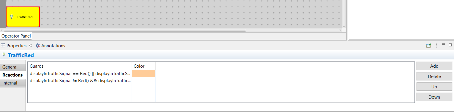

This item allows you to assign colors to certain input patterns. Switch to the Reactions tab inside the property section and add lines by clicking the Add button. In the guards column you can specify the input pattern and in the color column you can open the system color picker.
Use the Up and Down buttons to rearrange multiple rows as the input patterns are evaluated top down and the first matching pattern's color will be displayed.
Text Display


This item allows you to textually display output data. Multiple patterns can be entered using the Reactions tab in the property section and again mind the order of your patterns as they will be evaluated top down.
For simply displaying a port's value leave blank the guard column and enter the port's name in the Item input column.
But more complex assignments - even taking multiple ports into account - are possible as well. For a port of type int the following set of guards and item inputs would be possible:
| Guard | Item input | |
| port >0 && port < 10 | port | |
| port ≥ 10 && port < 100 | port / 10 | |
| port ≥ 100 && port < 1000 | port / 100 |
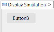
Using the Operator Panel in a simulation
Switch to a new simulation and unfold the tree until you see the enclosing component with the operator panel icon. You can either double click or use the context menu to open the operator panel.

Now you can either run or step through your simulation, alter your model's inputs and observe its behavior.
