Deployment Synthesis
The deployment synthesis enables to explore the allocation of tasks to execution units w.r.t. to the constraints and objectives described on this page.
As you can notice from some of the figures below, the defined constraints/objectives are listed as Target Definition in the DSE Navigator on the left.
Constraints
Allocation
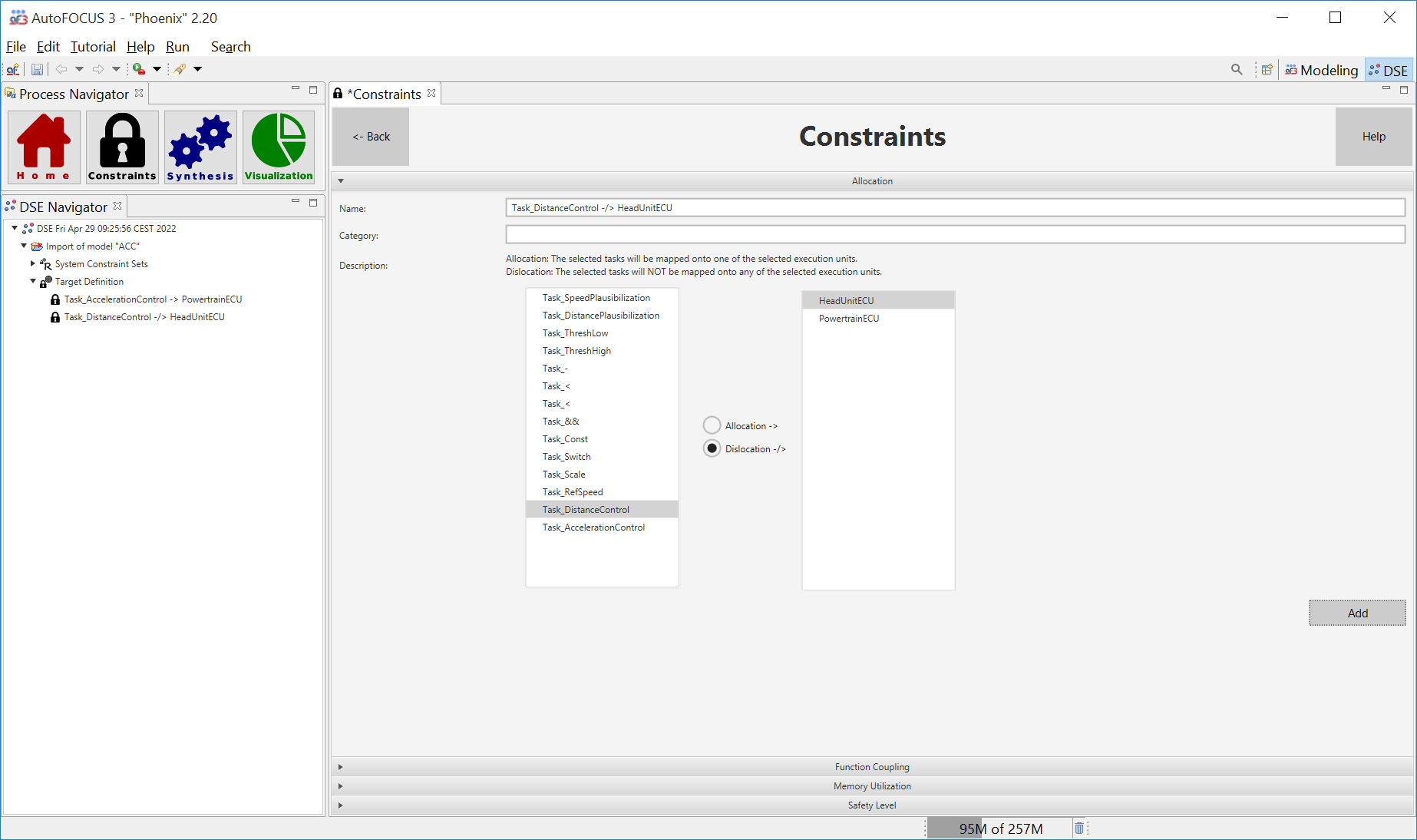
By selecting a task in the table on the left, and a (HW) execution unit on the right you can add an Allocation or Dislocation constraint.
- Allocation: the selected task(s) must be mapped to one of the selected hardware units.
- Dislocation: the selected task(s) must NOT be mapped to any of the selected hardware units.
Function Coupling
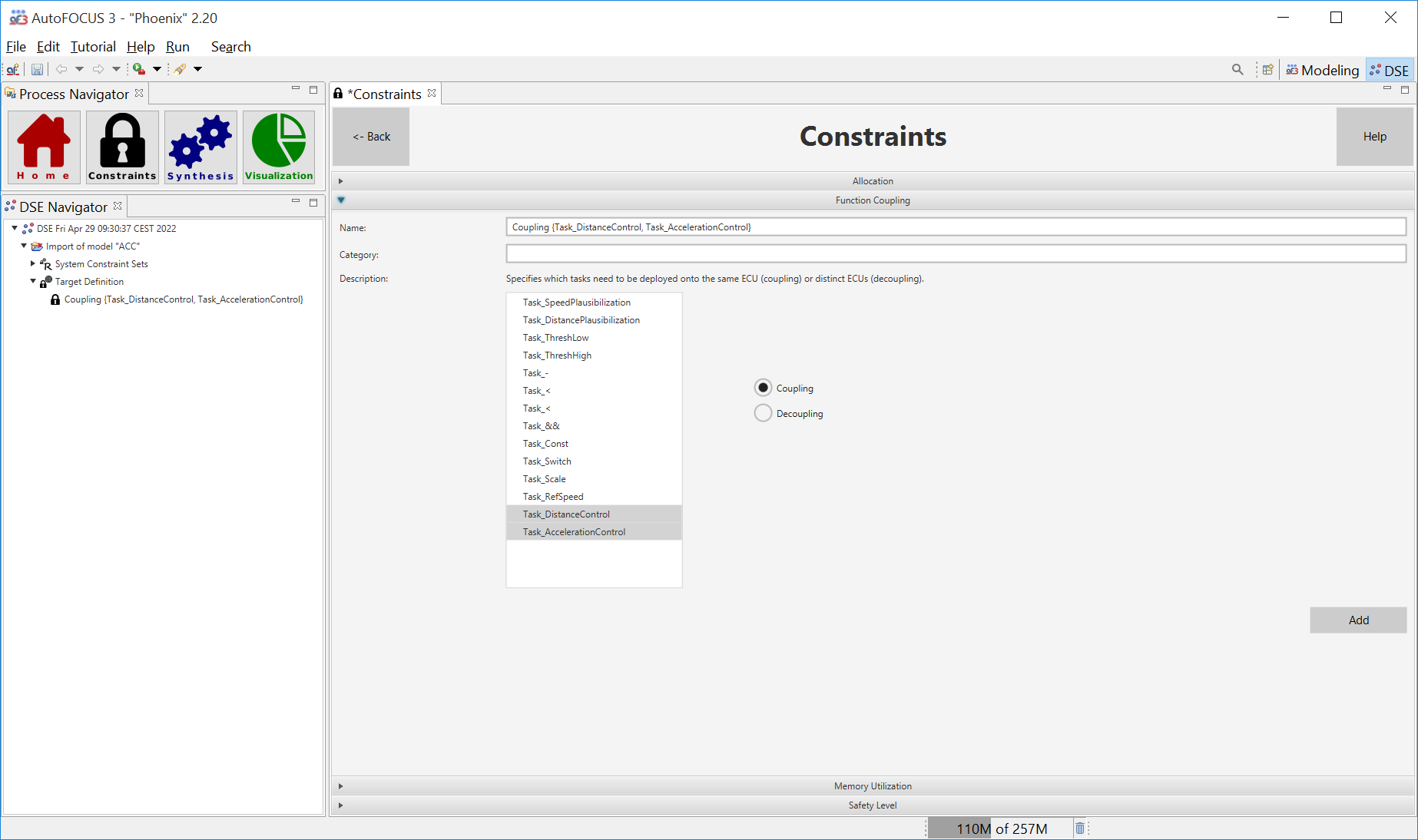
The Function Coupling Pattern you allows to force some tasks to be deployed into the same/distinct (HW) execution units. Note that the constraint does not specify to which HW execution unit the tasks should be allocated.
First select a set of tasks in the table on the left, and then select either Coupling or Decoupling in the option button on the right.
- Coupling: the selected tasks must be mapped to the same execution unit.
- Decoupling: the selected tasks must be to distinct execution units.
Memory Utilization
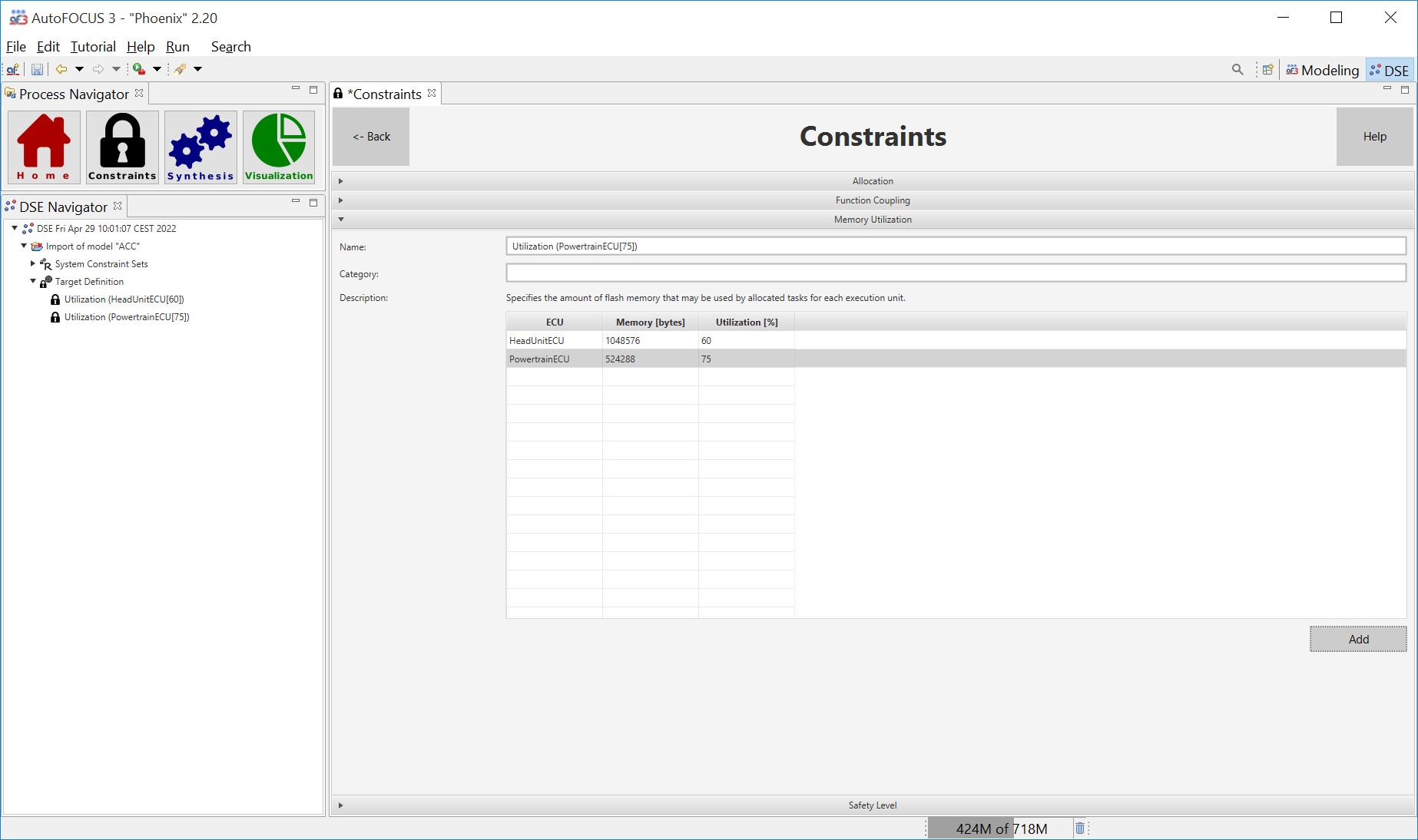
The Memory Utilization Pattern allows to specify the percentage of flash memory that may be used by tasks allocated to a given execution unit. As a prerequisite, the pattern requires the specification of the amount of available flash memory in the respective annotation of the execution units, and the flash requirements of Tasks in the Task Memory Mapping table, respectively (both in the Modelling Perspective). The admissible memory utilization ratio considered for the application of the constraint has to be entered into the second column of the table.
In the figure above, e.g., we are specifying that the tasks allocated to HeadUnitECU may only use up to 60% of the available 104876 bytes of flash memory.
Safety Level
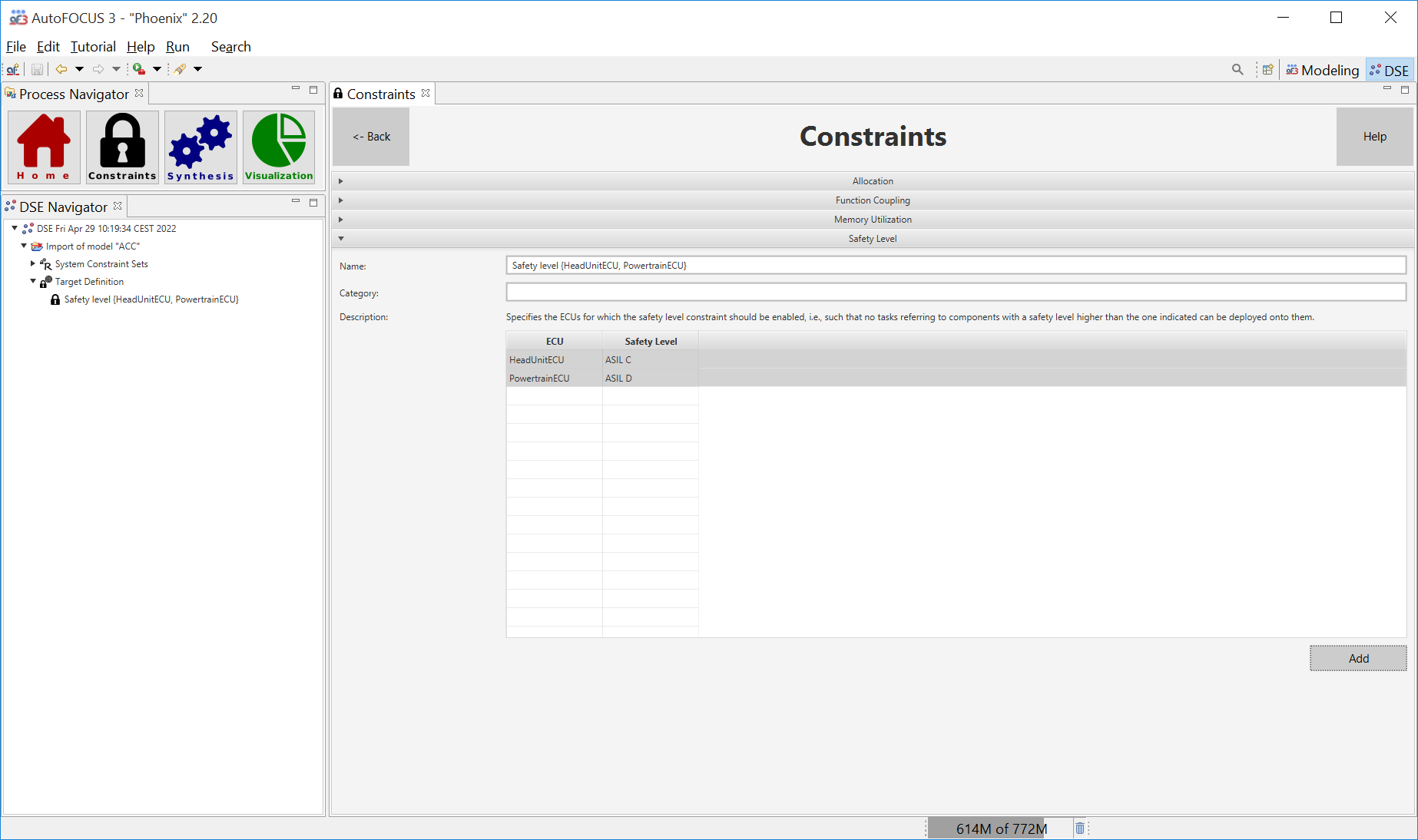
The Safety Level Pattern allows to specify the ECUs for which the safety level constraint should be enabled. This means that no tasks referring to components with a safety level higher than specified in the safety integratity level annotation of the respective execution may be deployed onto them.
In the example above, only tasks with an ASIL of up to ASIL-C may be allocated to HeadUnitECU (ASIL-D for PowertrainECU).
Objectives
Hardware Optimization
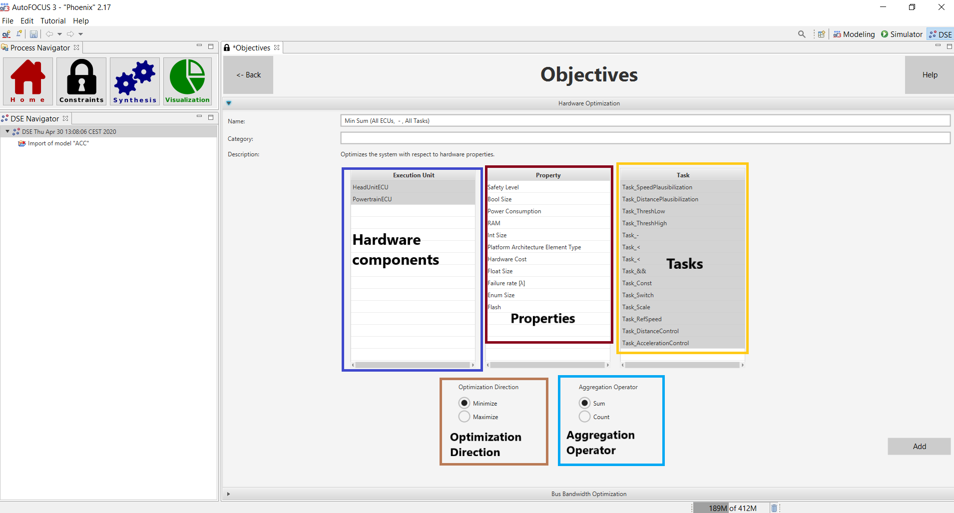
This pattern allows you to create optimization objectives for the hardware components (table on the left) where the tasks (table on the right) are running. The optimization function consists of two main parts:
- Optimization Direction: it can be either minimization or maximization of the function;
- Aggregation Operator: it can be either a sum over hw properties (e.g. the sum of the hardware costs) or count. The count function basically just counts the number of model elements (ECUs in this case) in an architecture.
Bus Bandwidth Optimization

This pattern allows you to optimize the bandwidth of a given transmission channel. You should first select the transmission unit you want to consider from the menu (in the figure above, InterdomainFlexRayBus is selected) and then select the optimization direction via the option button (either minimize or maximize). Finally press the button Add to create the objective.