FMI-based Co-Simulation with AutoFOCUS3, OpenModelica and Overture
Note:- The following example works as described on Windows only.
- Linux: A manual workaround is required as of now. Please contact us if you would like to try the example on this platform.
- macOS is not supported as of now.
Overview
System
The system to be simulated is an inverted pendulum mounted on a platform on rails. The pendulum's movement is parallel to the platform's tracks. Moreover, the inclination of the pendulum is assumed to be measurable. This results in a controllable system. The goal of the simulated system is not only to stabilize the pendulum given some disturbances acting on the pendulum. In addition, the inclination of the pendulum shall be able to be controlled by an input signal.

Illustration of the inverted pendulum.
Models
The environment model responsible for simulating the disturbances acting on the pendulum is developed in Overture by means of the Vienna Development Method (VDM). The input model providing the desired inclination of the pendulum over time is developed using AutoFOCUS 3, relying on the stream-processing semantics of the FOCUS theory. Finally, the system model including the dynamics of the inverted pendulum as well as the PID controller are modeled in OpenModelica leveraging the continuous semantics of the Modelica language and the vast libraries of the tool.
Setup
AutoFOCUS 3
- Install GCC as explained in the AutoFOCUS 3 co-simulation documentation
- Download the following AutoFOCUS 3 model: Input Model
- Import the project: 'File → Import AF3-Project'
Overture
- Download, unzip and launch Overture (tested with Version 3.0.0)
- Install the FMI exporter for Overture following these instructions: FMI support for Overture
- Download the following Overture project: Environment Model
- Import the project: 'File → Import... → General → Existing Projects into Workspace → Select archive file'
OpenModelica
- Download and install OpenModelica (tested with version 1.14.{1/2} (Windows/Linux)
- Download the following OpenModelica model: System & Controller Model
- Launch OMEdit - OpenModelica Connection Editor
- Import the project: 'File → Open Model/Library Files(s)' and open it by double-clicking openmodelica_system
FMU Export
AutoFOCUS 3
- Switch to the Storage perspective and create a folder within the AF3 workspace. FMUs cannot be exported to the workspace's root folder.
- Return to the Modeling perspective and export the Input component as FMU: '[Right-click on component] → Export to FMU 2.0'
- Set the component to be executed at a frequency of 100 Hz and store it in the previously created folder within AF3's workspace.
Overture
- Export the NoiseGenerator project as FMU: '[Right-click on project] → Overture FMU → Export Tool Wrapper FMU'
- The FMU will be stored in './generated' within the project directory.
OpenModelica
- Export the model as FMU: 'File → Export → FMU'
- The location of the newly generated FMU will be displayed in the console.
FMI-based Co-Simulation
OpenModelica
- Create a new simulation: 'OMSimulator → New OMSimulator Model'
- Make sure to set its type to Weakly Coupled (usually selected by default).
- Open the top-most component called Root by default and marked with a WC-icon (which stands for Weakly Coupled): Double-click on the component within the Libraries Browser.
- Add the tree FMUs previously exported like so: 'OMSimulator → Add SubModel'
- Connect the output of the input model (exported from AutoFOCUS 3) to the setpoint input of the system model (exported from OpenModelica).
- Connect the output of the environment model (exported from Overture) to the disturbance input of the system model (exported from OpenModelica).
- Instantiate the model by setting the Fixed Step Size to 0.01 and the Stop Time to 5: 'OMSimulator → Instantiate Model'
- Simulate the model: 'OMSimulator → Simulate'
- Switch to the 'Plotting' view (should happen automatically).
- Visualize the results by selecting the variables of interest in the Variables Browser:
- '[Name of the OMSimulator Model] → [Name of the root component] → System → angle'
- '[Name of the OMSimulator Model] → [Name of the root component] → System → setpoint'
- '[Name of the OMSimulator Model] → [Name of the root component] → System → acceleration'
- '[Name of the OMSimulator Model] → [Name of the root component] → System → disturbance'
With everything working correctly the following plots should be visible:

The setpoint and the pendulums angle.
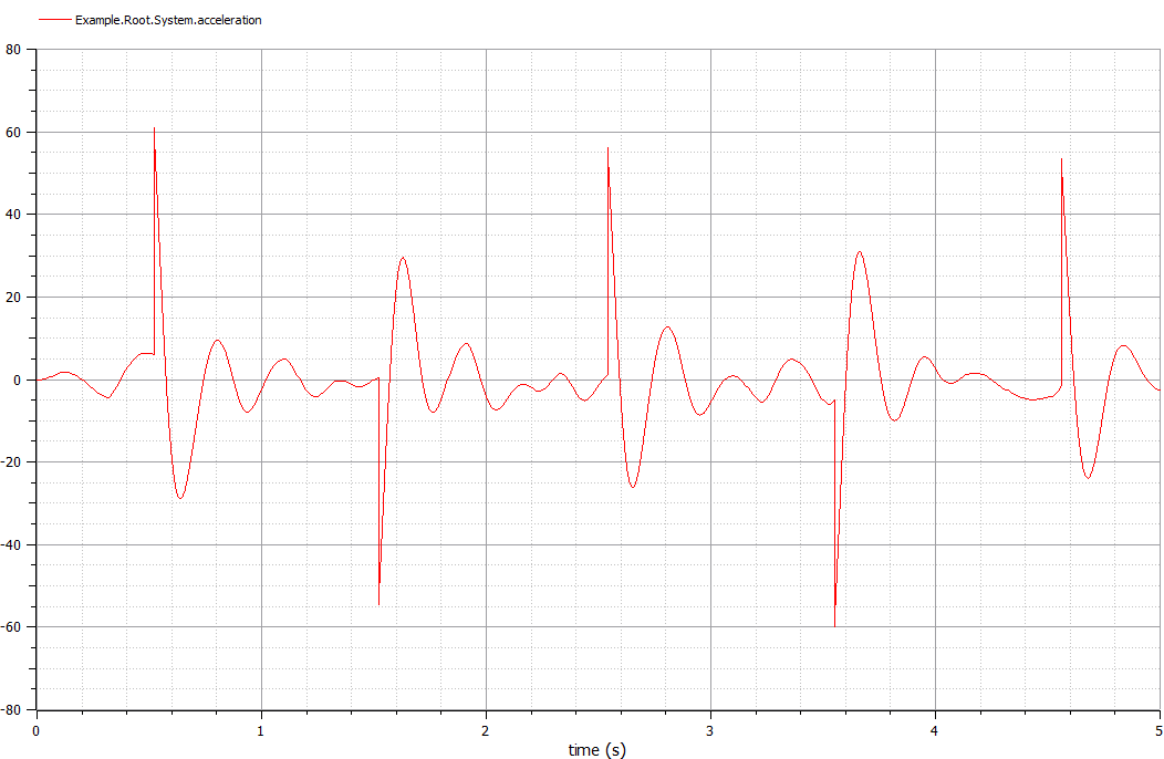
The acceleration to stabilize the pendulum.

The disturbance applied to the pendulum.