Creating a Mode Automaton
Following sections discuss motivation and steps to create Mode Automaton in AF3.
Motivation and Introduction
Beside the usage of State Automaton, there exists another way to model the behavior of components in a graphical Mode Automaton Diagram.
A component may contain some running modes, which should be used in distinct periods of the time. The control model for such modes is mode automaton. The usage of the mode automaton my have consequences on the code efficiency as well as on the correctness of the design. There are four kinds of the model elements in mode automaton.
Mode: A mode automaton contains at least one mode. A mode describes the current configuration of computational data flow a component is in. This configuration computes outputs for given component depending on the current inputs as well as the state of the local variables. A mode must have a sub component structure, in order to describe the current computation for the component. An initial mode, which the mode automaton starts with, is required in mode automaton.
Switch: Switch controls the change of the mode to execute. Switch element contains the Guards, which takes cares of the switch conditions.
Input and Output Ports: A port belongs to a mode, and is the start and the end of a switch.
Mode Component Structure: This model element contains the component architecture, which is used to compute the outputs when the corresponding mode active is. Every mode must contain one sub component structure. A mode component structure must have the same ports with the component, which contains this mode automaton.
Mode Automaton
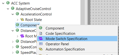
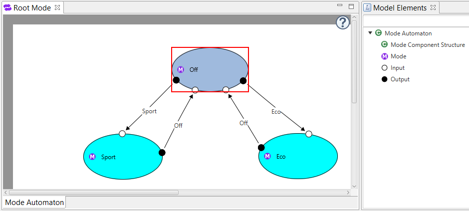
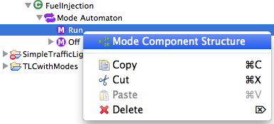
The mode automaton editor is very similar to state automaton editor. You can add a mode automaton to your component as shown in figure 1. In mode automaton editor, you might drag&drop a mode from the right Model Elements View to your diagram. In the same way you can add ports and mode component structure to your modes.
You can select the mode and drag it to everywhere in the editor. Same for ports, just pick them and move around the border of the mode. To resize a mode, pick the lower, the right, or the lower-right point of its bounding-box and then move it.
In order to create switches between your modes, press the <alt>-Key on your keyboard and drag the switch from one port to another port of different I/O-kind. You can also create the switch from one mode to another mode, new ports will be created automatically and the switch will be created between the new ports. Invalid switches (e.g., between two Output-Ports) are avoided by disabling the dragging.
Mode
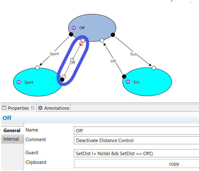
A mode automaton requires an initial mode. This can be done in the Properties View after you selected a mode. This mode is marked with a little black dot afterwards(see the following figure).
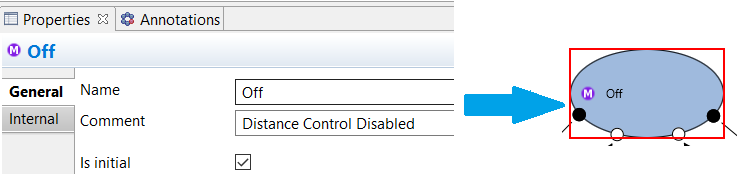
In the Properties View, you can also edit the names of selected modes and also specify comments.
Switch
Just like transition in state automaton, you can change the route of switches by selecting it, pick the point shown in the middle and move it. Afterwards, two new points are shown between the moved middle point and the two ports. By moving these points, you can further define the route more precisely. The conditions for switch between modes are done by specifying Guards of a switch. If no Guard of an outgoing switch is fulfilled, the current mode remains active. If a switch can be fired, then new mode will be active, and the sub component architecture of this mode will take over the computation job.
Note that, unlike transitions of a state automaton, mode switches do not have actions. Modifying the outputs should be done instead through component structure inside a mode.
Mode Component Structure
A mode generally contains a component structure. Editing such a structure is done in the same way as for Component Architectures. You can add a mode component structure as shown in the following figure.
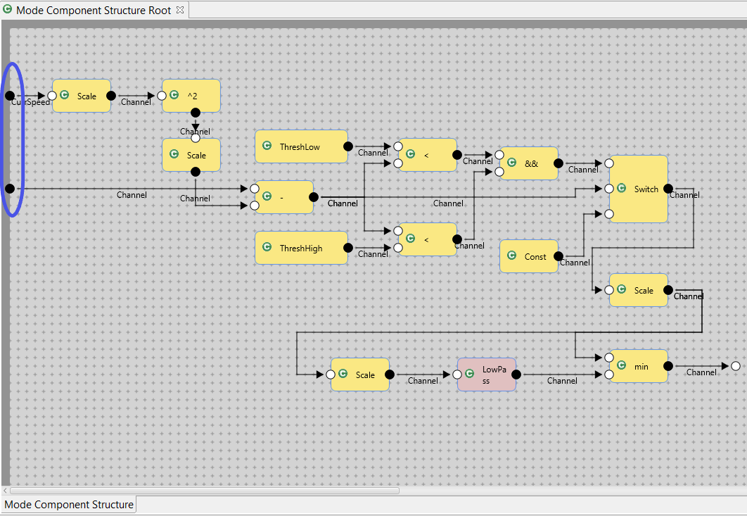
 The following figure shows an example of a mode component structure.
You can drag and drop the component and channels and like a component architecture.
The ports, which are highlighted in blue rectangles, should correspond to the ports of the component of the mode automaton.
The following figure shows an example of a mode component structure.
You can drag and drop the component and channels and like a component architecture.
The ports, which are highlighted in blue rectangles, should correspond to the ports of the component of the mode automaton.