Behaviour Simulation
Introduction
This section describes how to simulate the behavior of your components and its comprised state automatons. You can simulate your entire component architecture as well as only subcomponents of your architecture. Simulations can be influenced by manually setting values at input-ports of components. During the stepwise simulation, you can analyze:
- values of the input and output ports
- active state of a state automaton, as well as values of its internal variables
The Simulation Perspective
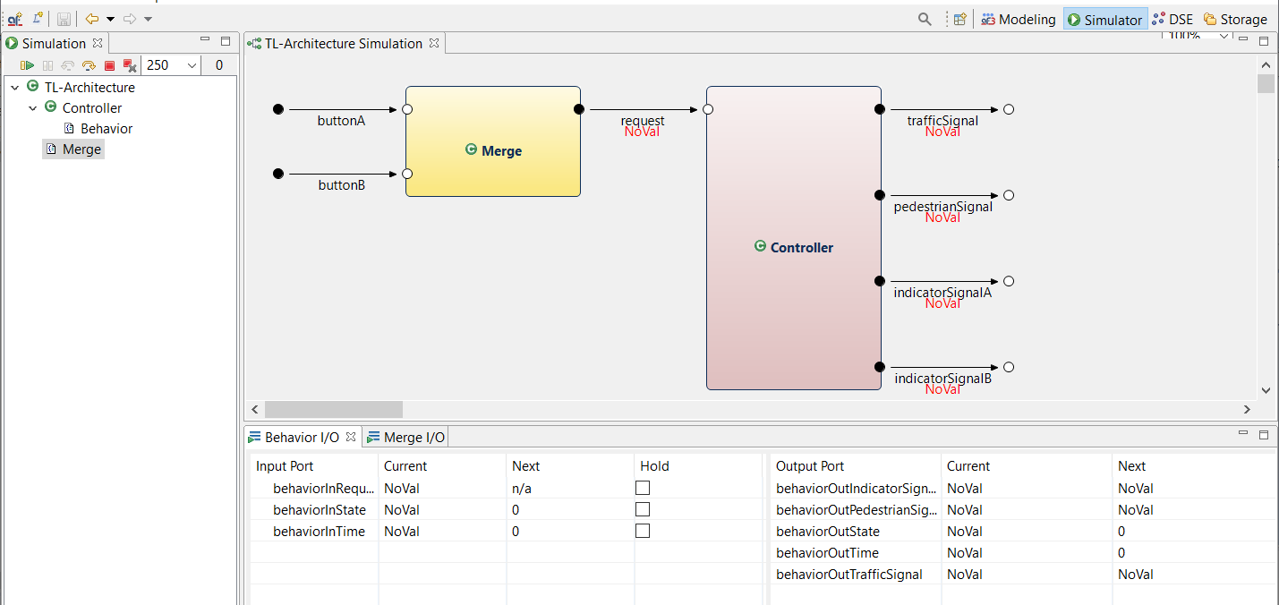
The Simulation Perspective contains three main areas.
- on the left side there is the Simulation View containing a tree of simulatable components
- on the upper right side the component architectures of composite components and the state automatons of atomic components are visualized, each in a separate view
- on the lower right side there are table views showing the values of the I/O-Ports of components and states, as well as the values of DataStateVariables
This is only a default layout. Of course you can reorder the complete layout regarding to your personal flavor.
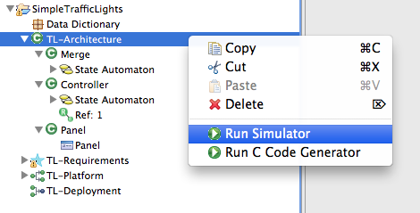
In order to execute a simulation, select a component in your Modeling Perspective, open the context menu (by right-clicking on it) and choose "Run Simulator".
After you have done this, the Simulation Perspective will appear automatically. (However, if your component architecture is not simulatable (e.g. because it has unconnected ports), then the Simulation Perspective stays empty and will not be opened.)
After the Simulation Perspective becomes active, initially you will see only the simulation view containing the tree of components. In order to open the other views, open the context menu of a component and select your desired view. For composite components, the Component Architecture View and the I/O View is available. For atomic components, the State automaton view, the I/O View and the Data State view can be selected.
Execute Simulations
You can execute simulations step-wise by clicking on the Simulation Step Button at the top of the Simulation View.
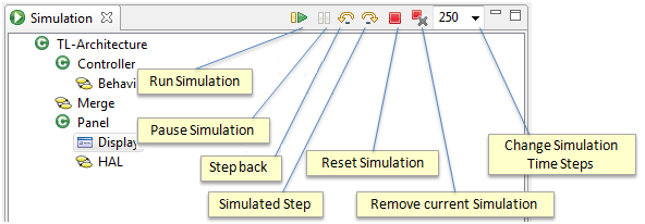
You can also execute multiple Steps by clicking the Run Simulation Button. After this, currently per default 4 simulation steps per second are executed until you press the Pause Simulation Button. After you have paused a Simulation, you can continue step-wise or per Run-Button. If you want to be back to the precise step of the simulation, use Step Back Button.
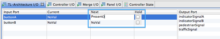
However, as long as you don't have specified some input values and all inputs stay on NoVal, nothing will happen during the execution steps apart from default initial outputs that will appear. Hence, you should specify a value of an input port first before performing an execution step. To do so, go to the I/O View (e.g., of your top level component) and insert a valid input port value.
Currently, unfortunately AutoFOCUS3 provides no support for choosing valid input values. You can figure out valid inputs by first discover the type of the port in your Component or State Automaton Diagram (inside the Modeling Perspective) and then have a look into your Data Dictionary to identify valid type-values. E.g., if the type of your port is a Enumeration called "Signal" having an Enumeration Member called "Present", you have to insert "Present()" as input value.
You recognize the insertion of an invalid input value, because the Invalid Type Error Marker doesn't disappear. If you leave the edit field while an invalid value is inserted, the value is reset to the original value.
Most often, you want to induce the value into the Input-Port only once, therewith the input will be NoVal at the next step. In this case, let the Hold-Checkbox beside the input field unchecked and the value will be reset to NoVal automatically at the next step. If you want that the input value is induced to the Input-Port at every step, activate the Hold-Checkbox.
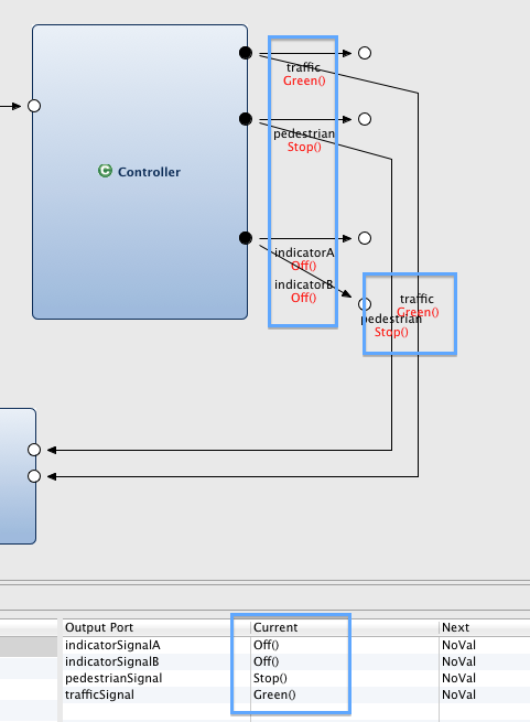
After you have inserted such an input value, the value of the respective channel in the diagram will change from NoVal to your inserted value.

Now, you might press the Simulation Step Button  . Because component Merge is weak-causal, the input value is directly influencing the output value at the same step, channelReq becomes also Present.
You can simulate an entire simulation sequence by performing the multiple simulations steps or pressing the Run-Button  . During this, you can obtain the behavior of your component (as black box view) by observing the values of the output ports or the channels. Hint: You cannot insert I/O values while the simulation is running. Please pause the simulation in order to input some values.
If all ports are valued with NoVal, this does not necessarily mean that the simulation sequence is over. Instead, the components might execute steps of their state automatons without doing some outputs. Hence, you should have a look to the state automatons also during the simulations.
Simulation of State Automatons
During simulation of State Automatons, the currently active state is marked in orange color while all other states are blue.
If your State Automaton has Data State Variables (DSV) and a Guard of an outgoing transition of the currently active state contains such a DSV, you should also have a look at the Data State View to observe the values of the DSVs.
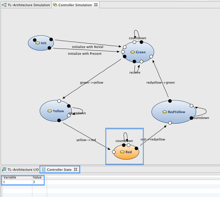
Only if all state automatons are waiting for input values (inside the guards of all outgoing transitions of all active states) and all ports are valued with NoVal, the simulation sequence is over and you should insert new input values.
You can also reset simulations to their initial state by clicking on the red Reset Simulation Button  .
.
Simulation using Operator-Panels
AutoFOCUS provides the possibility to add Operator-Panels to models in order to visualize model data during simulations as well as induce input data into the simulation. This is an alternative way to insert data in the I/O-Views.